How to use FILLET command in AutoCAD:-
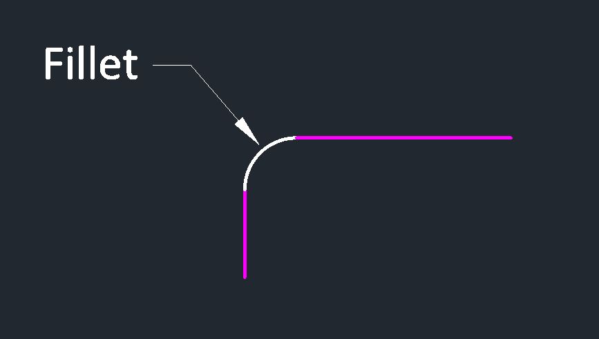
Fillet command extends two entities and draws a round arc between them. Fillet Rounds and fillets the objects
round or fillets the boundaries of two 2D objects or the flanking faces of a 3D solid.
An arc that is bent tangent among two 2D objects.
A curved changeover between two surfaces or adjoining faces on a 3D solid.
In this illustration, an arc is shaped tangent to the chosen lines, which are trimmed to meet the endpoints of the arc.
Some Recommended Posts:
In-Depth Introduction to Object Snaps In AutoCAD
How To Use AutoCAD Data Extraction Tool | Data Extraction To Excel
AutoCAD Free Download – Students Version
Top 20 Websites to Download Free CAD Blocks AutoCAD Blocks Download
Create 2D Fillets
A round or fillet can be shaped between two objects of the same or different object types: 2D polylines, arcs, circles, ellipses, elliptical arcs, lines, rays, splines, and xlines.
If the two selected objects are on the same layer, the arc defined is formed on that layer. or else, the arc is formed on the current layer. The layer affects object properties as well as color and linetype.
The subsequent prompts are displayed while creating a 2-dimensional fillet.
First Object
Select the primary of two items or the first line part of a 2D polyline to identify the fillet.
Second object or shift-select to apply corner
Select the second object or line segment of a 2D polyline to define the fillet.
You can also seize down the Shift key before selecting the second entity or line fragment of a 2D polyline to lengthen or trim the chosen items to form a jagged bend. While Shift is held down, a provisional value of “0” is assigned to the present fillet radius rate.
If the selected objects are straight line segment of a 2D polyline, the line segments can be contiguous to each other or divided by one supplementary segment. When the chosen segments are divided by a subdivision, the segment that separates them is detached and replaced by means of the fillet.
The bearing and distance end to end of the arc formed is determined by the points selected to select the objects. until the end of time select an object neighboring to where you want the endpoints of the fillet to be created.
Note:
adding together a fillet or surrounding to a hatch borderline that was defined with entity objects consequences in the elimination of hatch associativity. If the hatch border line was definite from a polyline, associativity is kept as original.
Command: FILLET enter
Select first object or [Undo/Polyline/Radius/Trim/Multiple]:
Select an object or enter an option
Select the second object:
Select the second object
RADIUS
Defines the radius of the fillet arc.
Enter fillet radius{current}: specify a radius or press enter
The value entered becomes the current radius for subsequent FILLET commands. Altering this value does not affect presented fillet arcs.
POLYLINE
Inserts fillet arcs at each vertex of a 2D polyline where two line segments meet.
Select 2D polyline: select an object enter
TRIM
Controls whether AutoCAD trims the selected edges to the fillet arc end-points.
Trim/No trim{current} : Enter an option or press enter
Trim – Trims the selected edges to the fillet arc endpoints.
No trim – Does not trim the selected edges.
How to use CHAMFER command in AutoCAD:-
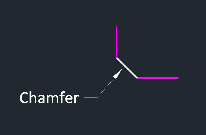
Chamfer command in AutoCAD Bevels the edges of objects.
Chamfer bevels the edges of an existing object.
Bevels or chamfers the edges of two 2 dimensional items or the neighboring faces of a 3D solid.
- An angled line that meets the endpoints of two directly 2D objects.
- A sloped transition among two surfaces or nearby faces on a 3dimensional solid.
The distances and angles that you indicate are useful in the order that you choose the objects.
How To Use Chamfer In Autocad, Autocad Chamfer 2d, Youtube Autocad Fillet, Autocad Fillet Trim, Autocad Chamfer 3d, Autocad Chamfer Command Shortcut
How To Use Chamfer In Autocad, Autocad Chamfer 2d
Create 2D Chamfer
A bevel or chamfer can be defined by selecting two objects of the same or different object types: lines, polylines, rays, and xlines.
If the two selected objects are on the same layer, the line defined is created on that layer. Otherwise, the line is formed on the contemporary layer. The layer affects entity properties as well as visual factors.
Here are the pomps that are shown in command line while creat 2-dimensional chamfer.
Command: CHAMFER enter
Polyline/Distance/Angle/Trim/Method/{select first line}: select a line
POLYLINE
Chamfers an entire 2D polyline.
Select 2D polyline: select a polyline
AutoCAD chamfers the intersecting line segments at each vertex of the polyline. Chamfers the new parts of the polyline.
DISTANCE
Distance option in chamfer command Sets the chamfer distances from the selected edge.
Enter first chamfer distance{current} :specify a distance or press enter
Enter second chamfer distance{current} :specify a distance or press enter
ANGLE
Sets the chamfer distances using a chamfer distance for the first line and an angle for the second.
Enter chamfer length on the first line{current} : Specify a distance or press enter
Enter chamfer angle from the first line{current} : Specify an angle or press enter
TRIM
Controls whether AutoCAD trims the selected edges to the chamfer line end-points.
Trim/No trim{current} : Enter an option or press enter
Problem:
Sometimes Fillet or Chamfer command is not working, and you may receive this message in the command line.
“Two entities are non coplanar” Or
“Line and polyline are non coplanar.”
There can be some reasons for this fault. However, one of the well-known reasons is that both the entities that you are trying to fillet or chamfer, are not on the same plane. This means that these entities have a different z value if you change the z value of both objects then the command will work.